There's been a lot of exciting stuff in space recently , Artemis II completed their missionhttps://www.nasa.gov/blogs/artemis/ 
, the ESA celebrated the first recieved signal from their CELESTE satelliteshttps://www.esa.int/ESA_Multimedia/Images/2026/04/Waiting_for_ESA_s_Celeste_first_navigation_signal , and a satellite broke aparthttps://earthsky.org/space/starlink-satellite-breaks-up-debris-artemis-risk/ . I was also watching the excellent Ringway Manchester channel, which posted a video the other week on GPS Jamming going on in Manchester the other week, due to a visit from the King: youtube.com: The Whole Of Manchester Was GPS Jammed. In it, Mr ringway goes and tries to observe the jamming, although sadly doesn't see any on his radio, so maybe it was only a reactive measure. But that got me thinking about playing around with a hackRF and receiving some GPS signals for myself.
- https://www.rtl-sdr.com/receiving-differntial-gps-beacons-with-a-hackrf/
- https://github.com/zraib/gps-sp-public
- https://www.rtl-sdr.com/using-a-hackrf-to-spoof-gps-navigation-in-cars-and-divert-drivers/
- https://gnss-sdr.org/conf/
For the absence of any doubt: I know next to nothing about radios, and this is me trying to figure it out. Anyone that does will likely find all sorts of inaccuracies and bungled analogies
How GPS works
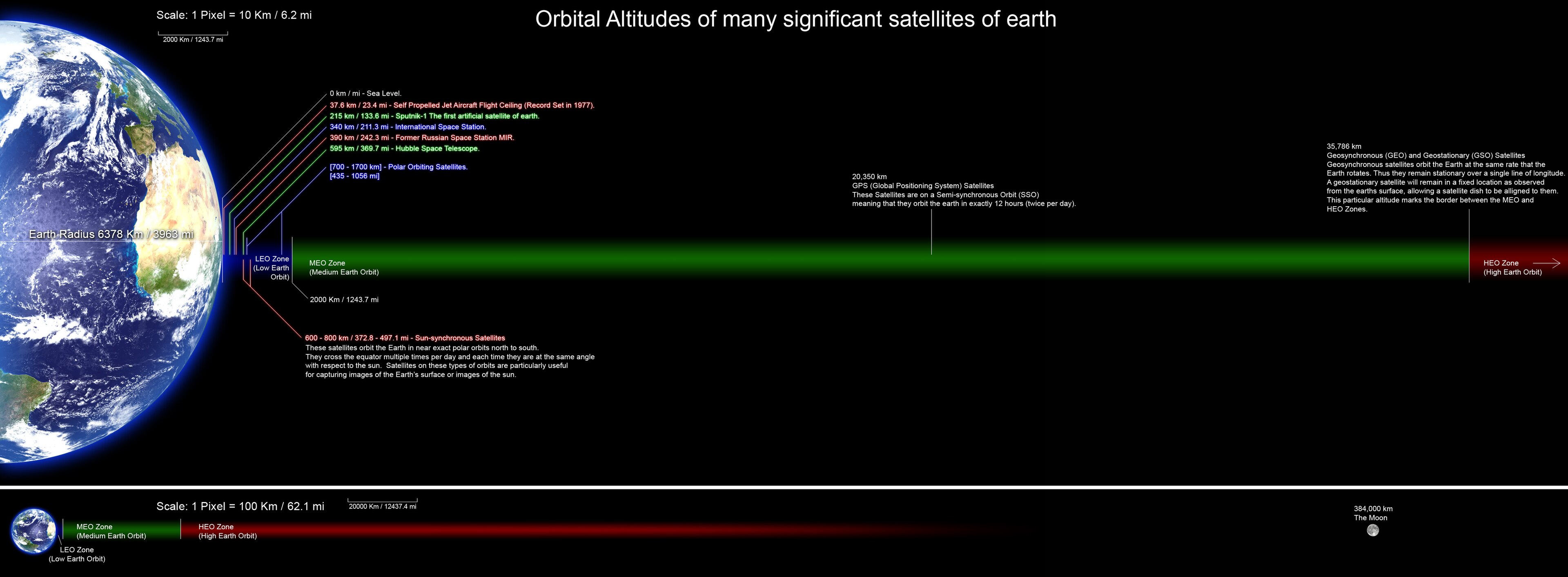
GPS works by positioning ~32 satellites around the world, in Medium Earth Orbit (MEO):
This model is AI built and potentially colossally inaccurate. I don't really care, it looks pretty
Then, GPS recievers can calculate their position by listening to the signals. Each satellite is equipped with high precision equipment to measure it's own position and a highly accurate time. The satellites transmit a data stream of their time and position. Receivers then use triangulation between 3 or more signals to determine their relative location.
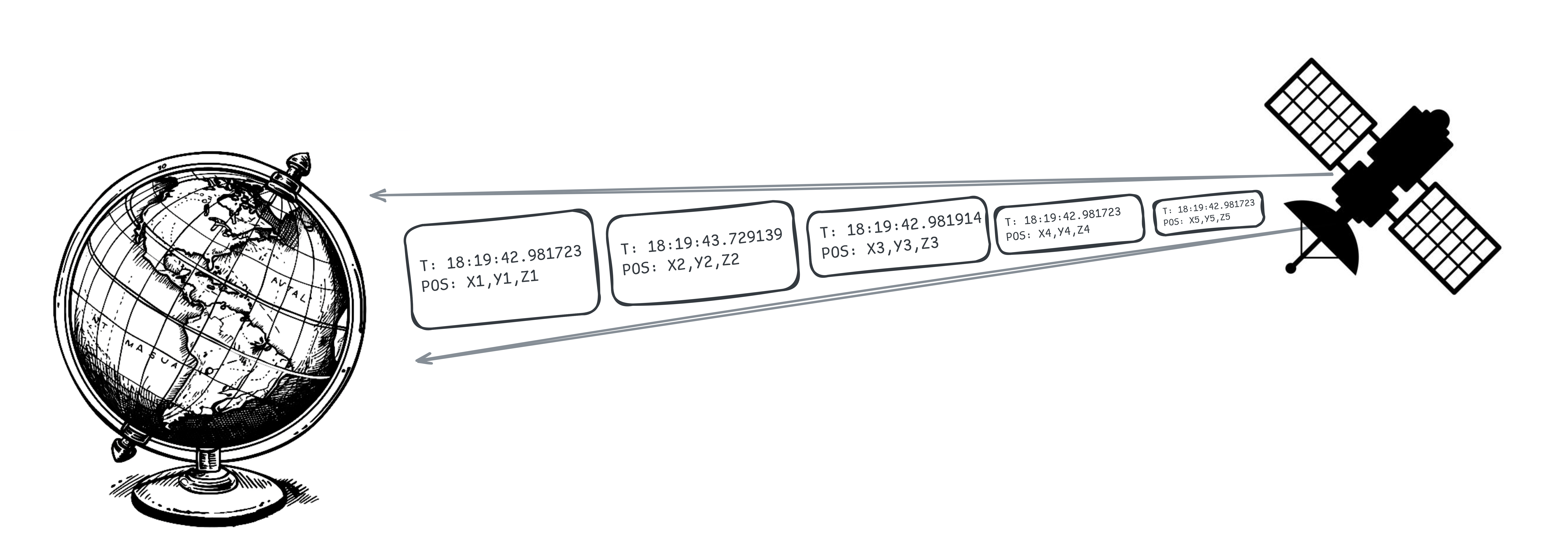 as we'll go into, this is a massively over-simplified version: the data isn't transmitted in packets like this
Military GPS has higher resolution, although in 2000 the gap was lessened.
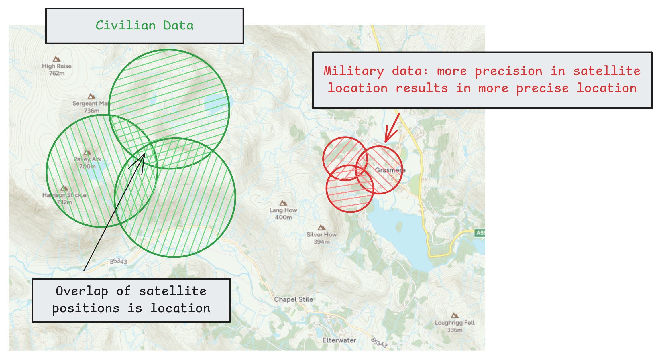
not to scale: Civilian data is ~ 10m accurate, military is ~1m accurate
Military signals are encrypted with a proprietary algorithm, and sent with a stronger signal strength, making it impossible to spoofWithout encryption keys , and harder to jam. Alternative systems, such as the ESA's GALILEO, are more accurate, roughly to less than 1m.
GPS is receivable from a mobile phone, so can be received with a small antenna, and without dedicated equipment, although the signal is apparently very weak. So it should be doable to receive with a hackRF right?
GPS antennas apparently are squarish and typically flat, pointing up
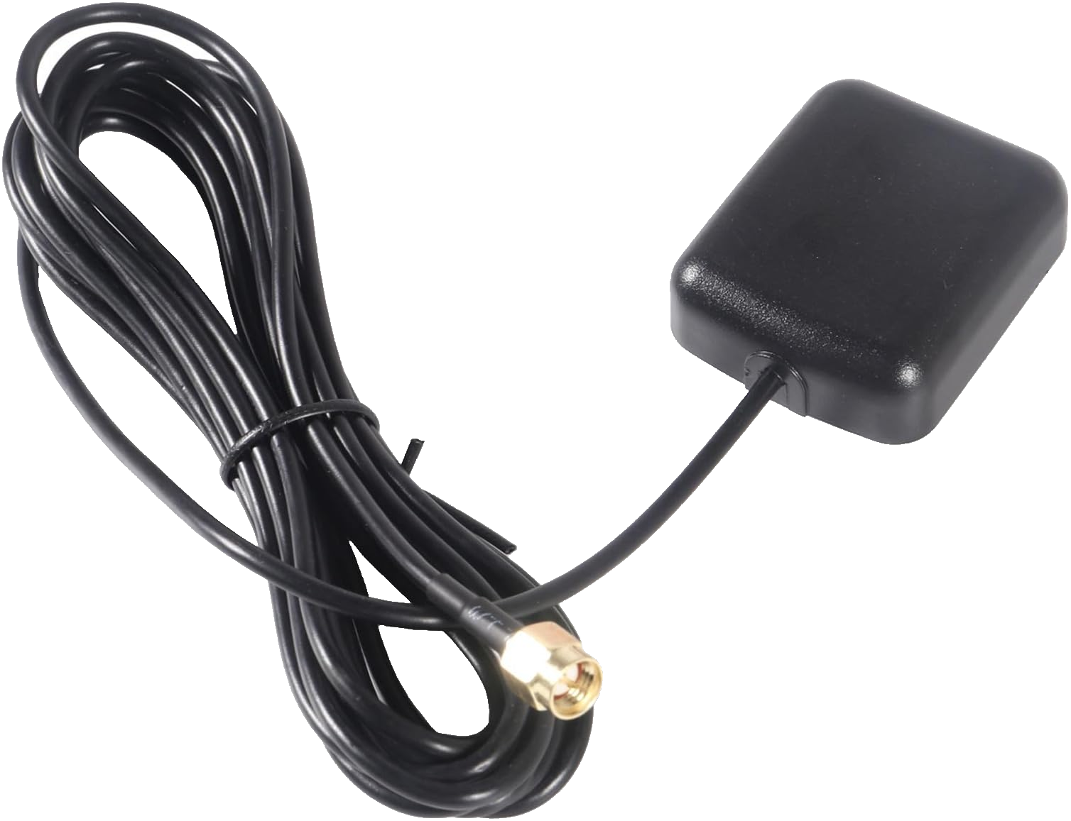
https://www.gps.gov/sites/default/files/2025-07/IS-GPS-200N.pdf
For rough comparison, here's a table of signal strengths of other common protocols. Note the -90dBm difference between received power of GPS and WiFi translates to roughly a billion times difference in signal strength.dBM is a measure of signal strength relative to 1 milliwatt: https://en.wikipedia.org/wiki/DBm. Since its
| Signal Type | Distance | Transmit Power | Received (dBm) | Received (Watts) | Reference |
|---|---|---|---|---|---|
| Mobile (4G): Outside, good coverage | 500m | +43 dBm / 20W | −70 dBm | 100 pW | 3GPP TS 36.214 |
| Mobile (4G): Inside / obstructed | 500m | +43 dBm / 20W | −105 dBm | 3 fW | 3GPP TS 36.214 |
| WiFi: Same room | 5m | +20 dBm / 100mW | −40 dBm | 100 nW | The Wireless Cookbook, page 13 & My laptop |
| WiFi: Across building | 30m | +20 dBm / 100mW | −75 dBm | 30 pW | The Wireless Cookbook, page 13 & My laptop |
| Bluetooth: Adjacent devices | 1m | +4 dBm / 2.5mW | −50 dBm | 10 nW | Bluetooth Core Spec 5.4 |
| Bluetooth: Across room | 10m | +4 dBm / 2.5mW | −70 dBm | 100 pW | Bluetooth Core Spec 5.4 |
| GPS L1 C/A | 20,200 km | +44 dBm / 25W | −130 dBm | 20 aW | IS-GPS-200, Table 3-V |
Table of signal strengths"My laptop" readings measured from my laptop with `sudo iw dev wlp82s0 scan | awk '/signal:/{sta=$2$3} /SSID:/{print $0" "sta}'`
GPS is divided into different channels, for example military vs civilian usage. The main channel, designated L1 Civilian (L1C), is the one we're interested in. Here's a table of the different channels, shamelessley robbed from Wikipedia (https://en.wikipedia.org/wiki/GPS_signals#Overview_of_frequencies):
| Band | Frequency (MHz) |
Phase | Original usage | Modernized usage |
|---|---|---|---|---|
| L1 | 1575.42 (10.23 × 154) |
I | Encrypted precision P(Y) code | |
| Q | Coarse/acquisition (C/A) code | C/A, L1 Civilian (L1C), and Military (M) code |
||
| L2 | 1227.60 (10.23 × 120) |
I | Encrypted precision P(Y) code | |
| Q | unmodulated carrier | L2 Civilian (L2C) code and Military (M) code |
||
| L3 | 1381.05 (10.23 × 135) |
used by Nuclear Detonation (NUDET) Detection System Payload (NDS): signals nuclear detonations/ high-energy infrared events. Used to enforce nuclear test ban treaties. |
||
| L4 | 1379.9133... (10.23 × 1214/9) |
N/a | ||
| L5 | 1176.45 (10.23 × 115) |
I | N/a | Safety-of-Life (SoL) Data signal |
| Q | Safety-of-Life (SoL) Pilot signal | |||
Trying it out
Okay, let's jump to plugging in the hackrf, booting up GQRX https://www.gqrx.dk/, and seeing what we see around the L1C channel, at 1575.42 Mhz.
In GQRX I selected the HackRF as a reciever, configured with the following settings:
- sample rate 40000000
- bandwidth: 2Mhz
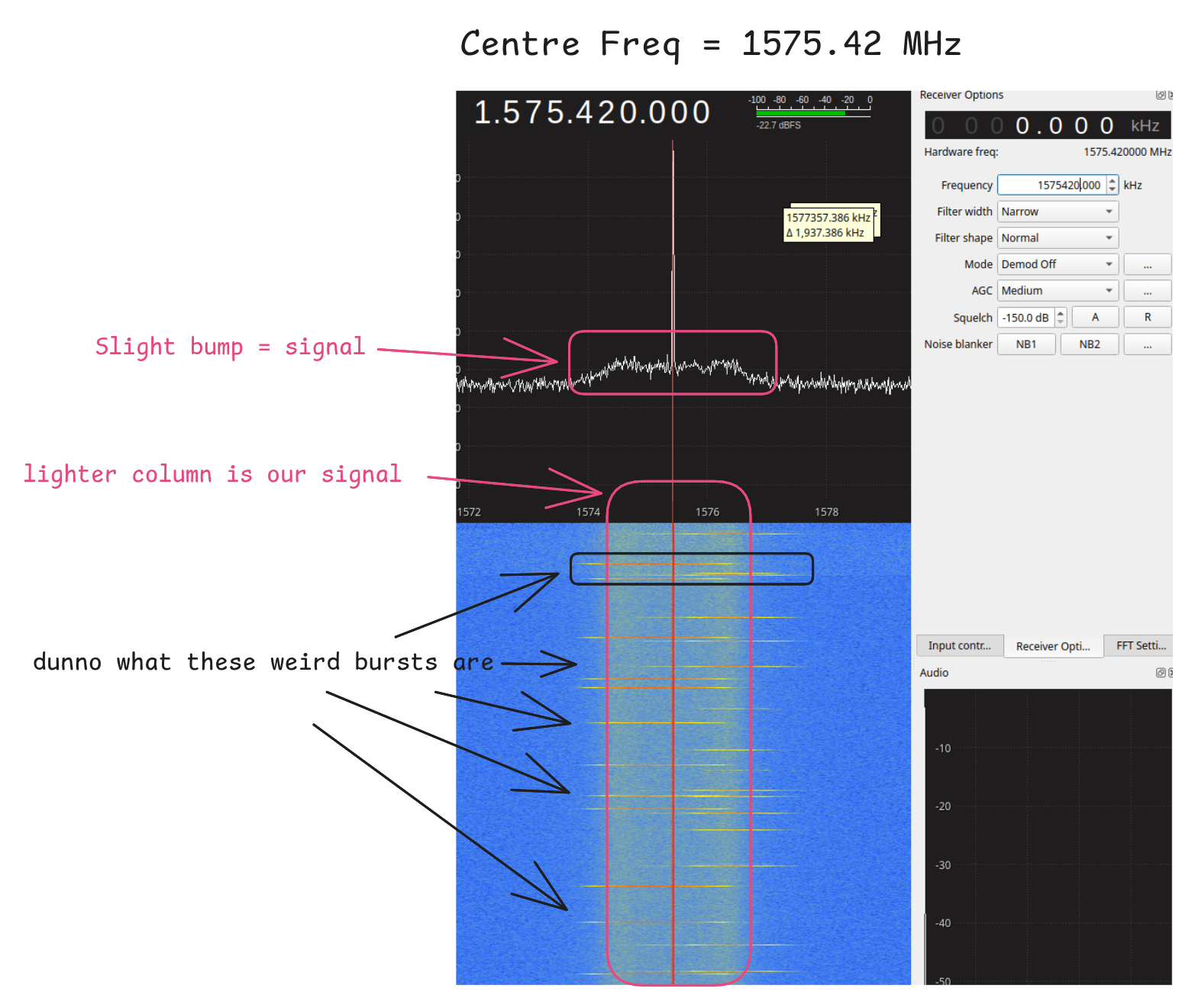
If we look at the waterfall we can see weird sharp bursts of data across the background signal. GPS is a continuous signal rather than distinct packets, so no clue what these odd bursts are, but GPS is the background.
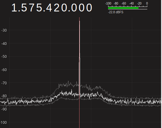
We can see a slight bump in the noise floor, but it doesn't really look like enough of a signal to extract data from? By holding at max, we can see the signal roughly makes a difference of 10dBm, and this is largely because of the intermittent bursts not the background.
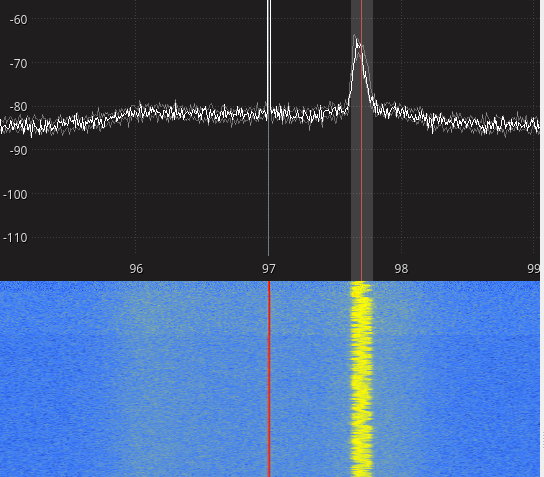
We can see the clear difference between this and a strong signal. To demonstrate this here's an example of a strong terrestrial signal: a radio station playing Iris by the Goo Goo dolls.
Then, when switching back to the GPS frequency, I found that I'd enabled some setting that was offsetting the frequency. So all the stuff I showed earlier about the GPS signal and the weird bursts on top of it was the wrong frequencyif it annoys you I wasted time explaining this, check the name of the blog . I also didn't notice that GQRX defaulted to displaying levels in dBFS, a different measure to dBm, so the figures on the left scale can't be compared to average noise levels for trying to find SNR. Here's the actual GPS signal @ 1575.42 MHz., measured in dBm at 50 ohms
Settings: Gain up, to see weak signals
- RF gain; 14dB
- IF: 32
- BB: 36
I adjusted the waterfall colouring as well, making it pick up weak signals better
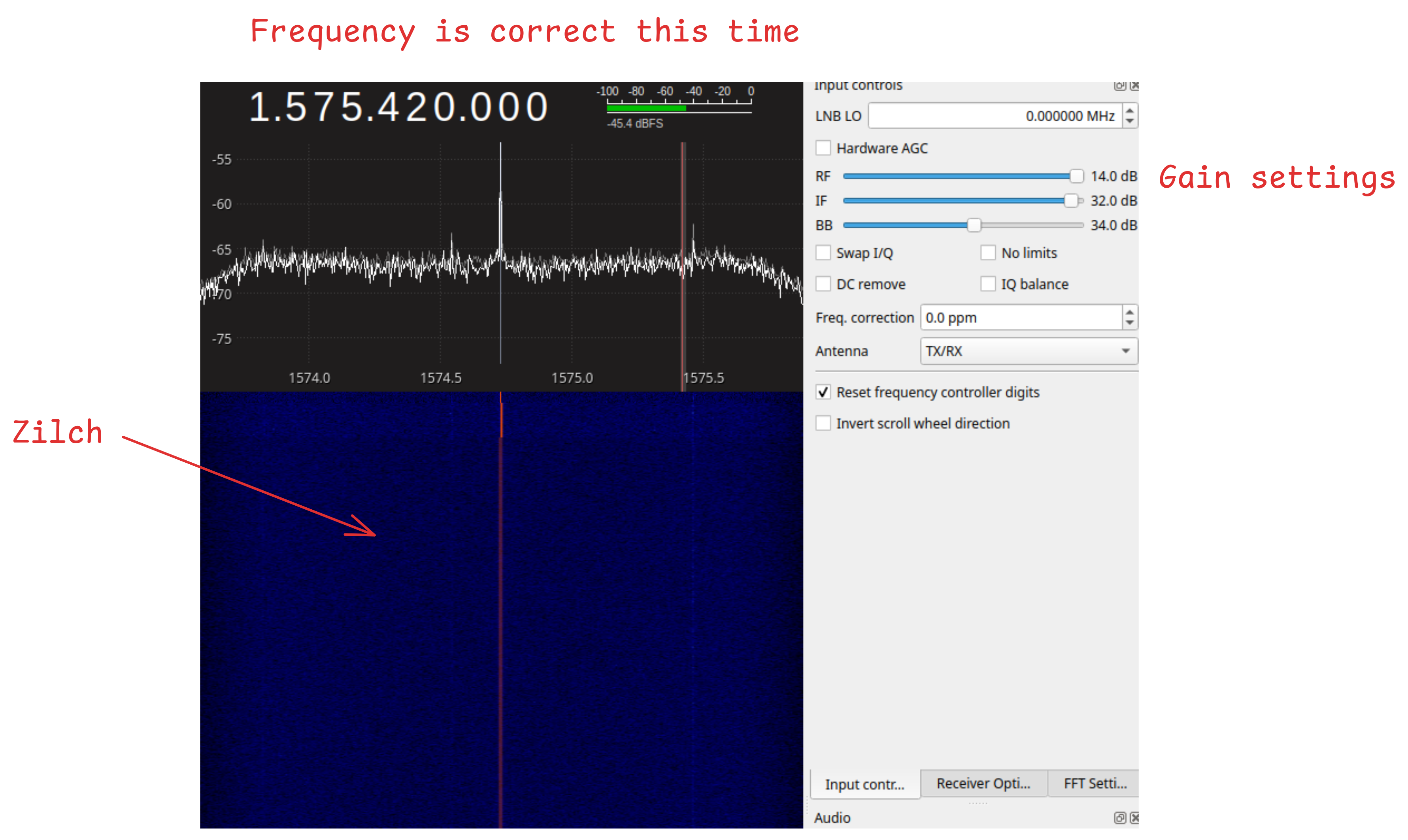
So now, we really can't see the GPS signal at all.
Not zilch??
Except, after a while, and playing around with the displayed freqs, I can make out some faint signals:
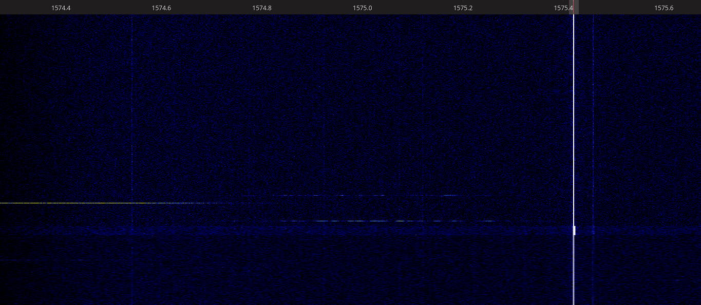
But, these are very faint etchings on the spectrum. Additionally they are narrow, static bands, so they can't be our GPS signal. That's for 2 reasons:
- GPS uses SPREAD SPECTRUM, smearing the signal over a wider band. In this case 2MHz
- GPS satellites are moving very fast: 14,000km/h. THeir signals are subject to doppler shift, and will appear to change in frequency as they move, so would result in diagonal lines
Here's what we might expect GPS to look like given the above properties:
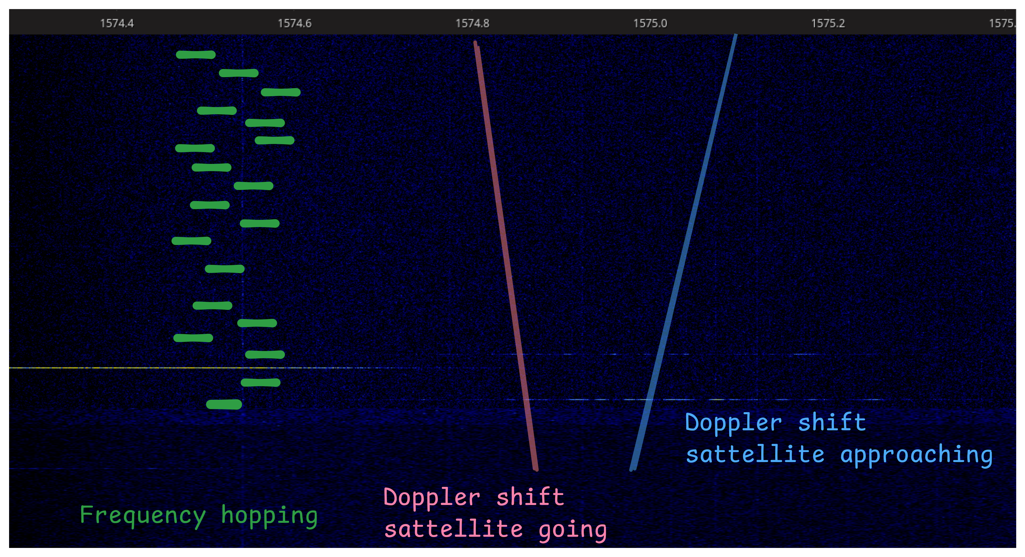 ignore the green signal on the left, turns out that's for "Frequency hopping" which isn't the same as "frequency spreading". Hopping results in short visible bursts at different frequencies, spreading just broadens the signal
Now maybe those are diagonal lines, just very slight. But they're definitely not spread, as we can see they have a narrow bandwidth.
And in fact, if we zoom out, we can see GPS: we were just too zoomed in. By adjusting the minimum frequency in the waterfall, we can see that in fact there is a band centred around 1575.42MHz of +- 1MHz:
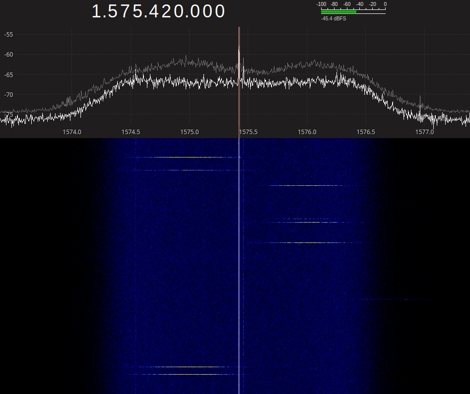
That whole dark blue band is the GPS signal, highlighted against the black nothingness of the background.
Now we have some kind of raw signal, can we process it to get live GPS data?
Bear in mind the current signal is from multiple overlapping satellites. And the entire point of GPS is to differentiate >= 3 signals. So we effectively have to split this into the different satellites.
Turns out this is done via something called Code Division multiple Access (CDMA), which i'm not going to pretend to understand super well
But is a form of Phase Shift Keying (PSK), where the data is modulated by flipping the phase of the signal, inverting the sine wave:
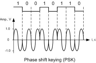
GPS works by allocating each satellite a unique Psuedo Random Number (PRN)https://www.gps.gov/pseudorandom-noise-code-assignments . The PRN is XOR'd with the satellite's data, and the result is used as the data to modulate the carrier frequency (1575.42).
Now, by looking at that wave, you can tell that you've altered the frequency of the signal. But you've altered it in a complex way, and therefore it is now described by multiple component frequencies
A good analogy for thisbearing in mind I dont really know what Im talking about here is a swing. Imagine you can see the 2 swings shown below:
If I told you the swings were being pushed by invisible ghosts, how many ghosts are pushing the left swing? 1 right. But the behaviour on the right can only be described by multiple ghost pushes, changing the direction of the swing and interferingAssuming 2 ghost's can't push at the same frequency and 1 ghost cant run around the swing at 2 different frequencies . So essentially this is how Phase Shift Keying makes 1 frequency into multiple frequencies.
So how does the receiver recover the original signal?
Well, they know the carrier frequency, and the PRN assigned to each satellite. So to find a signal, you iterate over each PRN and multiply it to recover the original signal, similarly to how XORing encryption works:
Sender:
sh
data × PRN × carrier = transmitted signal
Reciever
# generate
received signal × local carrier × local PRN = data
(data × PRN × carrier) × carrier × PRN
= data × (PRN × PRN) × (carrier × carrier)
= data × 1 × 1
= data
This is actually quite a cool idea, the intuition that channels must be frequency slices is so deeply ingrained from radio, TV, WiFi etc. that CDMA feels like it shouldn't work. But using random codes to "XOR" out the noise and recover the signal.
PRN RECOVERY
Okay, now I have a vague understnading of what's going on, can I apply it to my signal?
The steps for this are going to be:
- Record a sample of the 2MHz bandwidth
- Iterate over each PRN and recover the signal
- Identify which PRNs / satellites are in the data.
To record the data I attach the hackrf via USB, and use hackrf_transferhttps://github.com/greatscottgadgets/hackrf/blob/main/host/hackrf-tools/src/hackrf_transfer.c to record an iq file.
hackrf_transfer -r gps_sample.iq -f 1575420000 -s 4000000 -g 40 -l 32 -a 1 -n 40000000
-r gps_sample.iq — record to file
-f 1575420000 — centre frequency in Hz (1575.42 MHz)
-s 4000000 — sample rate (4 MHz)
-g 40 — VGA/baseband gain (0-62)
-l 32 — LNA/IF gain (0-40, in steps of 8)
-a 1 — enable RF amplifier (bias-T / front end amp)
-n 40000000 — number of samples to capture
 hackrf_transfer -r gps_sample.iq -f 1575420000 -s 4000000 -g 40 -l 32 -a 1 -n 40000000
call hackrf_set_sample_rate(4000000 Hz/4.000 MHz)
call hackrf_set_hw_sync_mode(0)
call hackrf_set_freq(1575420000 Hz/1575.420 MHz)
call hackrf_set_amp_enable(1)
samples_to_xfer 40000000/40Mio
Stop with Ctrl-C
 7.9 MiB / 1.000 sec =  7.9 MiB/second, average power -12.2 dBfs
 8.1 MiB / 1.000 sec =  8.1 MiB/second, average power -14.3 dBfs
 7.9 MiB / 1.000 sec =  7.9 MiB/second, average power -13.4 dBfs
 8.1 MiB / 1.000 sec =  8.1 MiB/second, average power -12.2 dBfs
 7.9 MiB / 1.000 sec =  7.9 MiB/second, average power -13.0 dBfs
 8.1 MiB / 1.000 sec =  8.1 MiB/second, average power -12.6 dBfs
 7.9 MiB / 1.000 sec =  7.9 MiB/second, average power -13.3 dBfs
 8.1 MiB / 1.000 sec =  8.1 MiB/second, average power -12.7 dBfs
 7.9 MiB / 1.000 sec =  7.9 MiB/second, average power -13.8 dBfs
 8.1 MiB / 1.000 sec =  8.1 MiB/second, average power -12.1 dBfs
 0.3 MiB / 0.029 sec =  9.0 MiB/second, average power -9.8 dBfs

Exiting...
Total time: 10.02924 s
hackrf_stop_rx() done
hackrf_close() done
hackrf_exit() done
fclose() done
exit
I quickly opened the file to check to see the signal was intact. Except... it wasn't. It just looked like white noise...
This is shown in the tool urh, designed for offline signal analysis, vs GQRX which is for live viewing, so the waterfall plot uses a different colour scheme
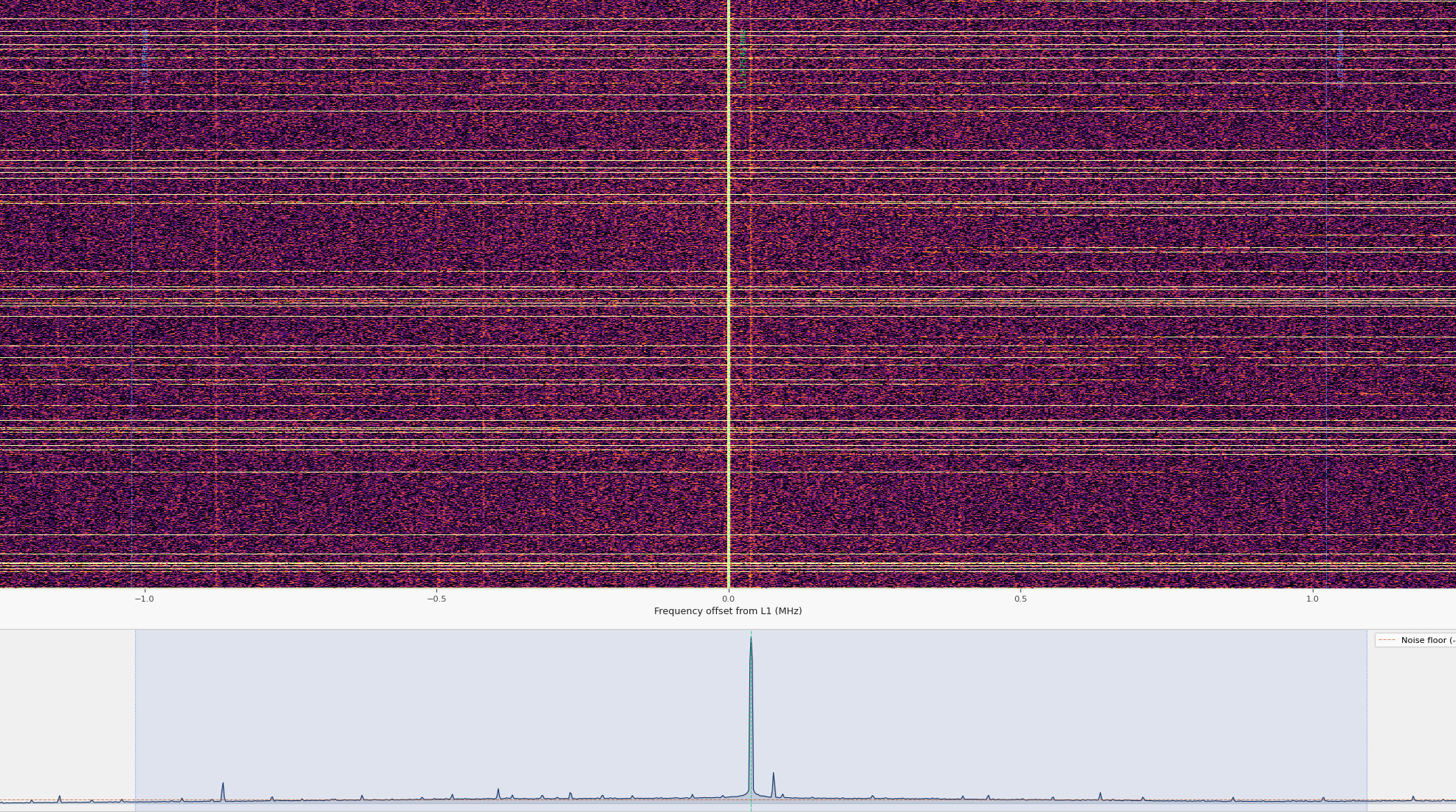
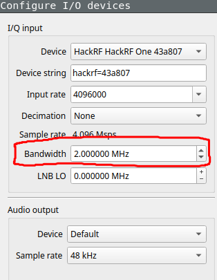
At this point I realised that the last experiment, in which I observed the GPS signal, I'd misconfigured the bandwidth on the device setting to 2Mhz. This effectively caused that 2Mhz bump, it wasn't GPS but the device settings. The reason that there was no signal on either side of the "GPS" bump was that the hardware was pre-filtering the data before it reached the SDR software, and only exposed 2MHz. It's not a hard cut off, and some strong signals outside of that range could still be seen in GQRX
Opening the signal analyser again, this time with the device bandwidth set to 4MHz, the signal disappears:
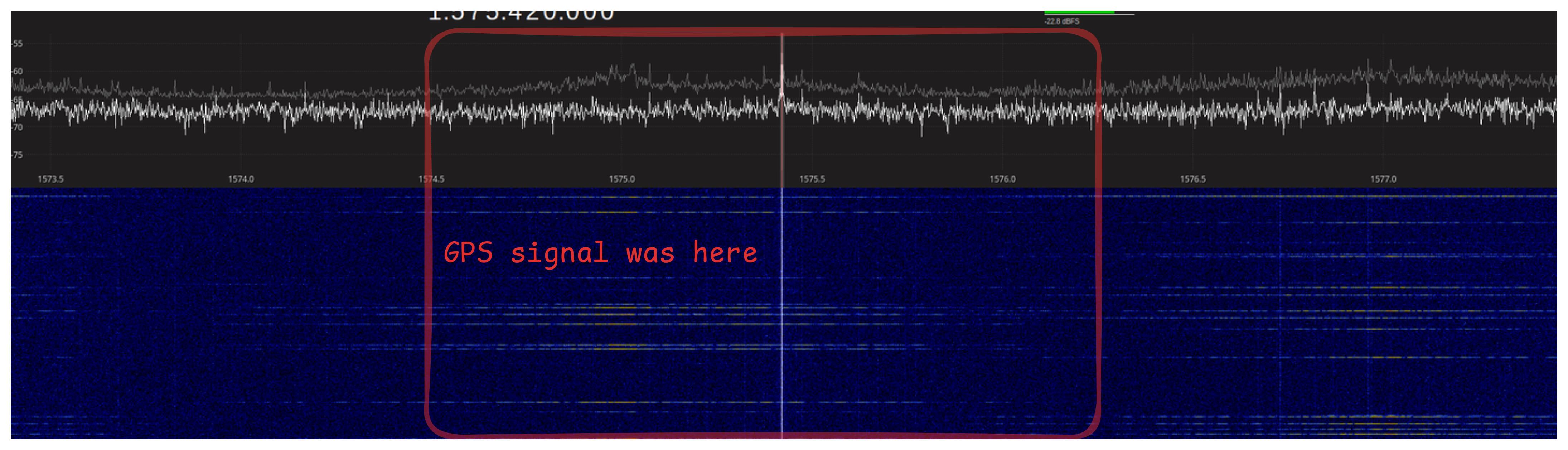
So I've fucked up again, and I never got a GPS signal.
Boosting the signal
Okay back to square one: I never had a signal to process so need to go and get one. That means I need to find a way to boost the weak signal.
The reason the weak signal can't be seen is because it's overwhelmed by noiseWikipedia: Nyquist Noise https://en.wikipedia.org/wiki/Johnson%E2%80%93Nyquist_noise . The original signal is transmitted through space and reaches the antenna. The antenna converts it into current via the movement of electrons. But all the components that current travels along already have noise from the thermal energy within the atoms. Over the course of the path from the signal to the receiver chip, the noise can add up to overwhelm weak signals. Noise depends on the temperature and resistance of the materials, but is estimated to be −174 dBm/Hz at room temperature.
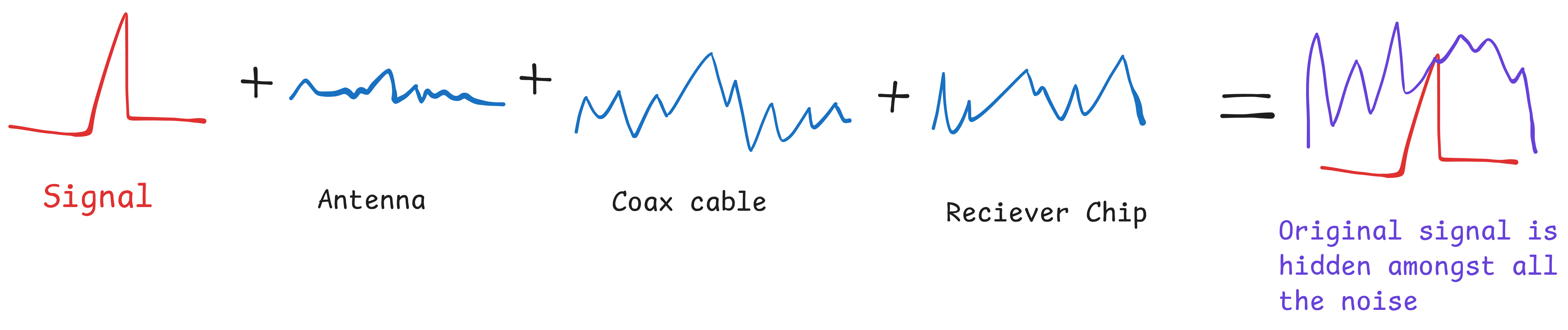
The ratio between signal and noise is denoted Signal to Noise Ratio (SNR), here we have a low SNR, since our signal is consumed by the noise.
So I looked into solutions for this, and found a very convienient one: a Low Noise Amplifier (LNA)https://medium.com/cyberpath-technology/testing-open-source-sdr-labs-20-db-lna-how-20-amplifier-boost-signal-strength-401e315f4b79 https://www.onesdr.com/2024/06/07/what-is-a-bias-tee/ . What this does is to amplify the antenna's signal by using a separate power supply to mimic the signal recieved, overcoming the noise from other components, using a transistor.
In fact, my HackRF kit came with one, I just never knew what it was before. Here's an image of what it looks like:
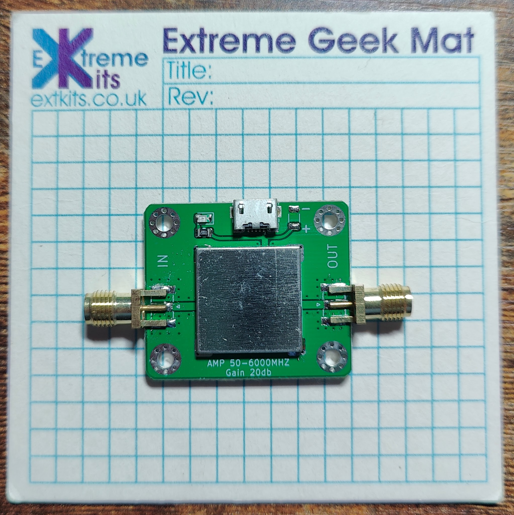
We attach it between the antenna and the HackRF, and it recieves it's own power supply, which is what provides the strong signal to HackRF.
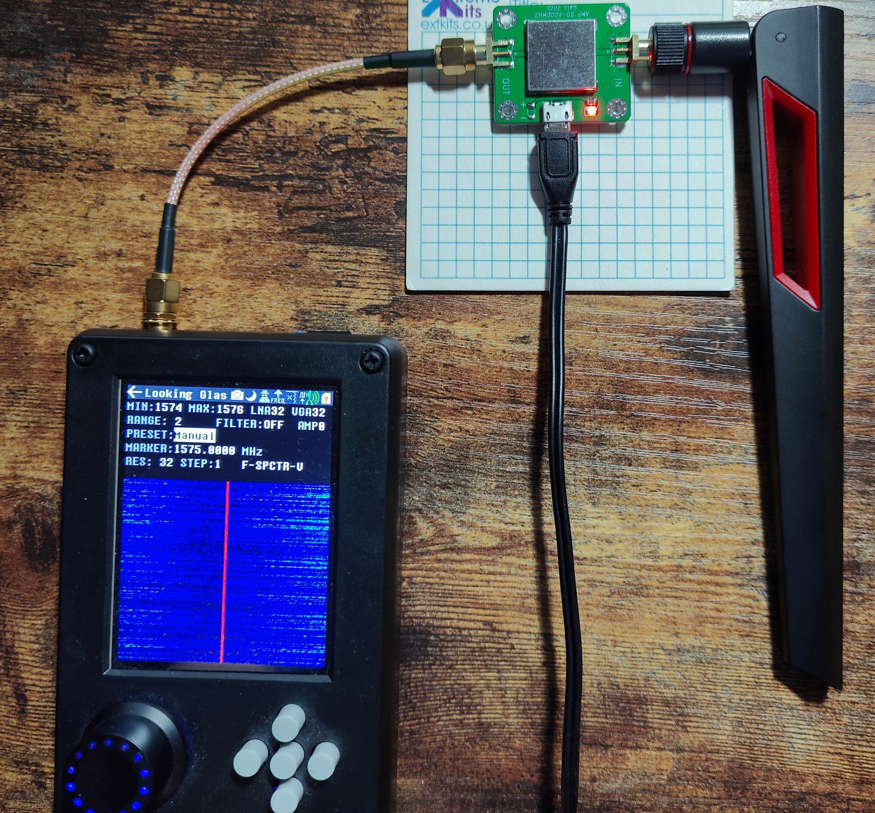
Looking at the before and after the LNA is powered on, we can see a clear boost to the signal:
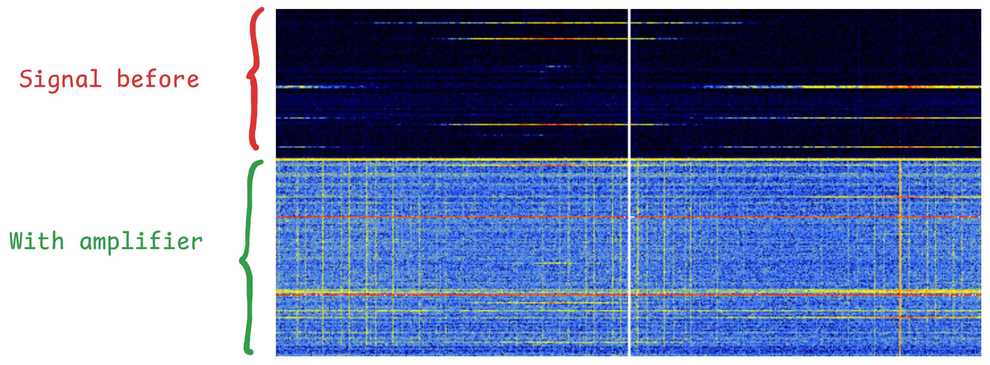
We can see tons of signals within the noise we previously couldn't, although no clue what they are. Maybe echoes of other signals? although they look a bit strong for that.
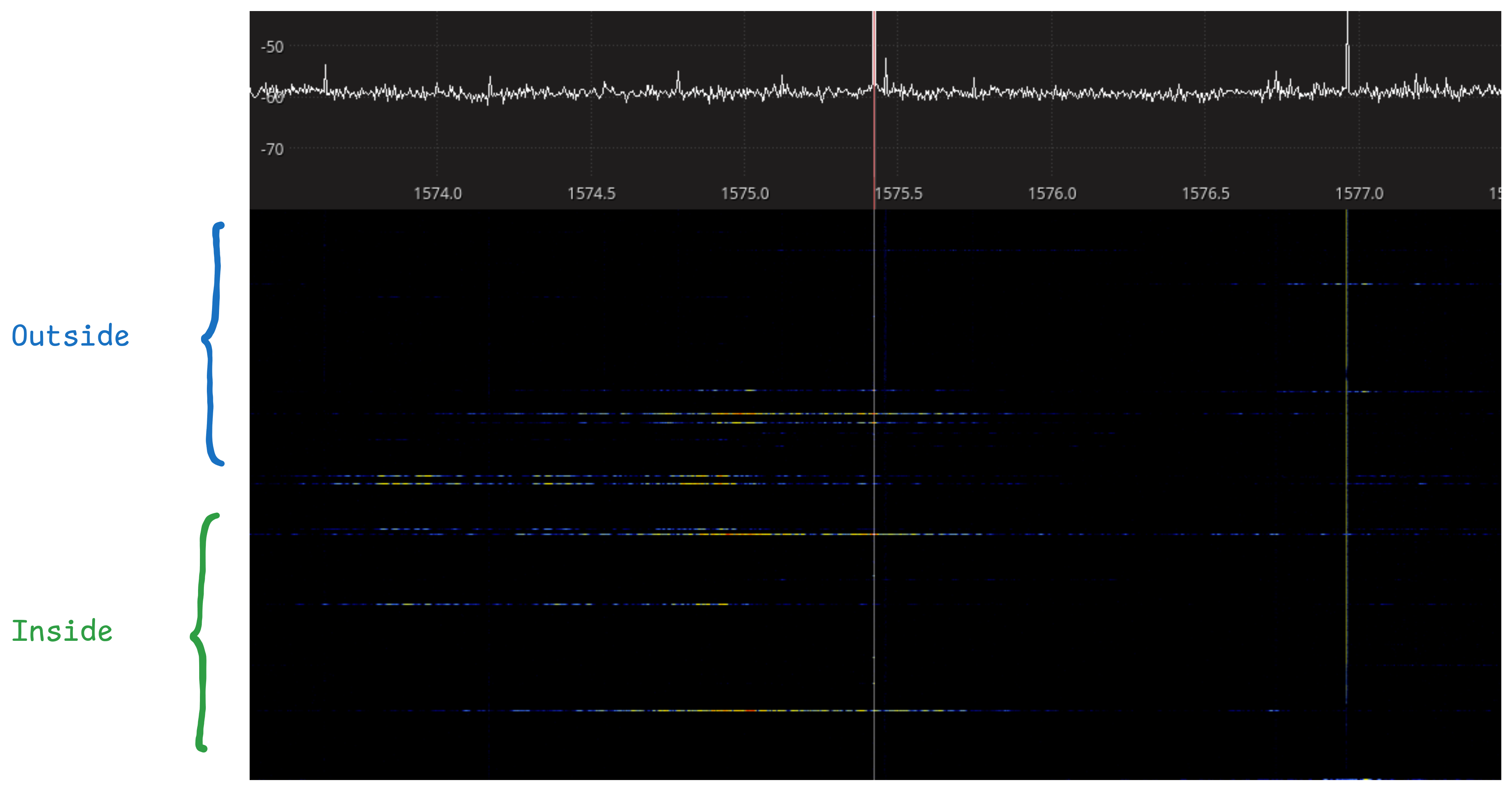
Currently I'm recording the signal from inside, while the building is wrapped in scaffolding. So maybe being inside is the issue?
To test I stuck the hackrf out the door, although still under the scaffolding, and saw no difference
Still under scaffolding, so probably not great
Better Data
A couple of days later I went out in the sunshine and recorded another sample in a park, away from scaffolding, one with the LNA and one without.
Will this signal be good enough to decode GPS signals? We'll find out in part 2.
Summary
Stuff wot I learned
- How GPS works
- just how weak GPS / other sattelite signals are
check your hardware settings when recording radio signals
check the software settings, and adjust
double check hardware settings
Why noise occurs in signal recievers
wot LNA's are and why they're useful
Frequency spreading and how it's different from frequency hopping